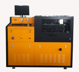
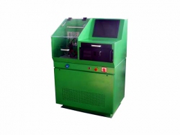
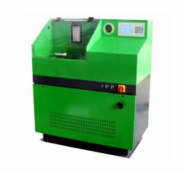
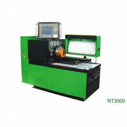
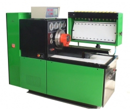
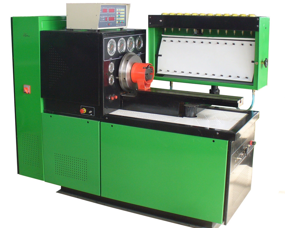
Стенд ТНВД 12 PSB (114-108)
 Есть в наличии
Поставка стендов ТНВД 12 PSB из Китая по разумным ценам.
Предназначение стенда – диагностика, проверка и регулировка ТНВД разного производителя (отечественного и импортного), включая дизели всех типов: рядных - BOSCH/ZEXEL, LUCAS/DELPHI, DENSO, MOTORPAL, и распределительных - Bosch, Lucas, Zexel, Denso.
Данные стенды имеют такие положительные стороны: высоконадежные, обладают низкой шумностью, используют минимальное количество энергии, имеют высокую испытательную точность, обогащен полной функцией защиты, разработана удобная операция и способ эксплуатации. Он относиться к лидерам в стране по числу продаж своих аналогов.
Отдельные опции:
- TRAVEL OF TOOTH BAR: USD 285
- OIL LUBRICATE: USD 750
- FORCED COLLING: USD 750
Характеристика и функции стенда ТНВД 12PSB:
- возможность развивать скорость в диапазоне 0-4000 оборотов за минуту;
- 12 цилиндровый топливный насос;
- имеет в распоряжении 10 передач;
- присущий в конструкции источник ответвления 12В/24В;
- температура контролируется индикатором на цифровом дисплее;
- наличие БПП;
- функция проверки откачивающего количества насоса и расхода насоса, также давления корпуса насоса VE;
- испытательная функция на герметичность;
- смазка машинным маслом, если есть необходимость;
- равномерная подача топлива по всем секциям;
- получение параметров углов подачи топлива ТНВД;
- испытание параметров ТНВД распределительного типа;
- проверка корректора по надуву.
| Модель | 12PSB |
| Выходная мощность | 7,5 / 15 (кВт) |
| Напряжение | 380В/50Гц, 3 фазы (или по запросу) |
| Двигатель | AC двигатель |
| Коробка передач | Конвертер |
| Скорость оборотов | 0-4000 об/мин |
| Высокий вал | 125 (мм) |
| Колличество цилиндров | 12 |
| Предварительное установление передач (кол-во) | 10 |
| Цифровая индикация подачи | Да |
| Цифровая индикация температуры | Да |
| Предварительный установленный БПП | Да |
| Проверка откачивающего количества насоса VE | Да |
| Проверка расхода насоса VE | Да |
| Проверка давления корпуса насоса VE | Да |
| Испытание температуры | 40±2 |
| Подача насосов двигателя | 1.1 (кВт) |
| Штрихи подсчета | 50~999 |
| Стандарт инжектора | ZS12SJ1 |
| Объем испытательной емкости для масла | 40 (Л) |
| Маленький мерный цилиндр | 45 (мл) |
| Большой мерный цилиндр | 150 (мл) |
| Измеритель цвета | LZB-10 |
| Источник постоянного тока | 12/24 (В) |
| Высокое давление испытательной подачи масла | >4 (МПа) |
| Низкое давление испытательной подачи масла | >0.4 (МПа) |
| Манометр для VE насоса | 0~1.6 (МПа) |
| Манометр для VE насоса | 0~0.16 (МПа) |
| Размер упаковки (ДxШxВ) | 2.45x1.14x1.83 (м) |
| Вес | 860 (кг) |
| Вес брутто | 880 (кг) |
1. FEATURES
By employing high performance/low noise inverter and using Bosch advanced techniques Our testbench has had more and more advantages, such as, wide range of adjustment speed, stable speed, large torque outputting, easy operating and so on. This test bench used digital indicators to display speed, counting, test oil temperature,1 pressure/vacuum and advance angles.
The test bench of NT3000 and 12PSB series in it’s 12 cylinders with 5.5/7.5/11/15/18.5/22kw motor, can start and test both in-line and rotary fuel injection pumps, for example, , , , A, B, P, Z, VE pumps and so on, by employing the suitable accessories.
2.Main function
- Measurement of each cylinder delivery at any speed.
- Test point and interval angle of oil supply of injection pump.
- Checking and adjust the mechanical governor.
- Checking and adjusting the distributor pump.
- Experiment and adjusting of behavior of supercharging and compensatory device.
- Measurement of oil return of distributing pump
- Testing of the electromagnetic valve of distributor pump.(12V/24V)
- Measurement of the internal pressure of distributor pump.
- Checking of the advance angle of advance device.(on request)
- Checking the sealing of injection pump body
- Install tube of auto-sucking oil supply can check on oil supply pump(including VE pump.)
- Checking the travel of stroke (on request)
CHARACTERISTICS
- Chaning frequency changing rotational speed
- Low fall of rotational speed and high output torque
- High measurement precision;
- The functions of over voltage, overload and short circuit protection;
- Ten classes Rotation speeds presetting;
- Constant temperature controlled;
- Ultra low noise;
- Operating position: arbitrary side of the two work sides of the test stand;
- Rotation speed, count, temperature, air pressure, advance angle and rack travel are measured and controlled by computers in real time, then displayed by 17″CRT or on request (17 LCD touch screen).
- Built-in air resource;
- All data can be made into reports and printed;
- Automatically generating and displaying speed characteristics curve;( tooth bar stroke)
- The data of the pumps can be saved, modified and obtained pump database;
- It is very easy to find the data of the pumps in pumps database;
- Windows operating system.
3. TECHNICAL DATA
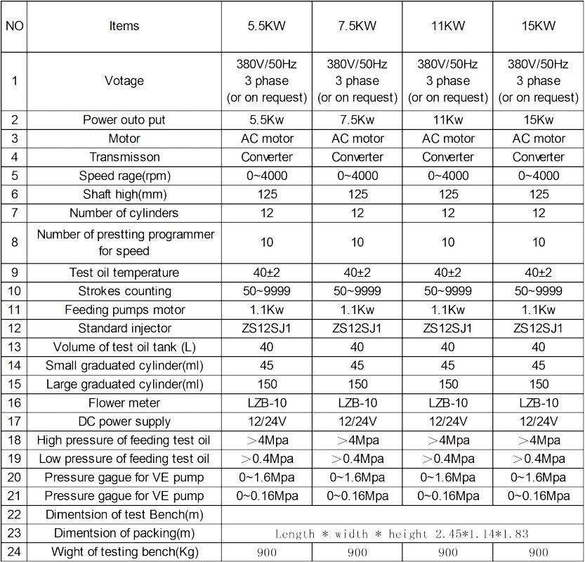
4. BRIEF INTRODUCTION OF MAIN STRUCTURE
4.1 Main body of test bench.
It is a structure made of tubular steel bars. The motor directly drivers the flywheel and graduated disc, and drivers tested pumps by flexible coupling. On the top of test stand the controls is supported.
The main body name shown as following:
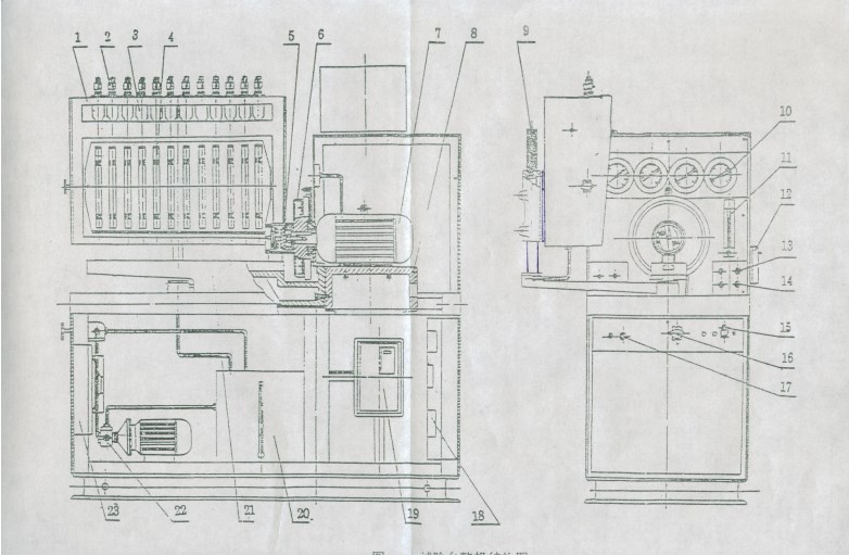
- Injector measuring system.
- standard injector
- Collection cup
- Graduated cylinder (or called Glass tubes)
- Flexible coupling.
- Graduated disc.
- Main motor.
- Support for main motor.
- Raising and dropping device.
- Pressure gauges.
- flow meter
- controller(Speed sensors)
- union for test oil return union for 0~1.6Mpa pressure gauge
- union for feeding test oil
- output of pressure air
- adjusting valve for test oil pressure
- fuse for DC12/24v
- Switch board
- Frequency converter
- Test oil tank
- Working table
- Test oil feeding pump
- Radiator for test oil
-
4.2 Injection measuring system.
It is to measure each cylinder’s delivery of tested pump. The box body is supported by the rotary arm. The rotary arm with the box can be rotated for 180?. Such, the reading front can be present on both sides of the test stand. The graduated cylinders are inserted on both fronts of the chassis, the big one on one side and the small ones on the other. The chassis can be overturned by hand-wheels both for discharging and positioning the graduated cylinders to be used. The counting process controlled by delivery count and relevant switches. If necessary, the whole box can be raised and dropped to test different4 pumps.
The following are for Fig 2.
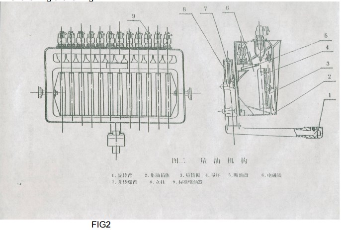
- Rotary arm.
- Box body.
- Chassis for graduated cylinders.
- Graduated cylinder. / glasses tubes
- Plate for blocking oil.
- Solenoid contactor.
- Up-down screw bolt.
- Pillar.
- Standard injection.
5. TRANSMISSION SYSTEM
5.1 Transmission system
In this system there are inverter, motor, fly-wheel (graduated disc) and flexible coupling and so on . the inverter controls the motor running. The motor directly drives the flywheel, and drivers tested pump through flexible coupling.
By the magnet steel which was inlayed at the flywheel, the sensor can pick up the signal of rotary speed ,then send the signal to the rotary speed indicator and stroke counting indicator to display.
5.2 Frequency conveter controlling motor
5.2.1 Principle
There is a relationship between motor speed and supplied frequency to motor. The relationship is as following:
N=120F (1-S)/P
N: value of rotary speed. F: Value of supplied frequency to motor.
S: value of ship. P: number of motor pole.
Obviously there is a direct ratio between “N” and “P” is a constant and “S” also is almost a constant.
5.2.2 Connecting the Freqency Converter
The 3-phase electrical supply was connected to the terminals (L1, L2, and L3) OF5 Conveter through switch. The terminals (T1, T2, T3) of inverter were connected to the main motor. The terminals (1, 2, 11) of inverter controlled the main motor to run as clockwise /counter clockwise rotation and to start or stop. The terminals (13, 15, and 17) of inverter were connected to he speed adjusting potentiometer.
6. TESTIN OIL SYSTEM
6.1 Technical data of this system
a. Volume of test oil tank: 40L
b. Pressure of feeding test oil:
- Low pressure: 0~0.4Mpa.
- High pressure: 0~4Mpa.
c. Feeding capacity of test oil: ≥10 L/min.
d. Stabilization temperature of test oil by automatic: 40±2 .
e: Heater: 1Kw/380V.
6.2 Principle of test oil system
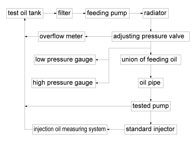
6.2.1 Principle drawing of test oil system
The drawing is shown as Fig. 1
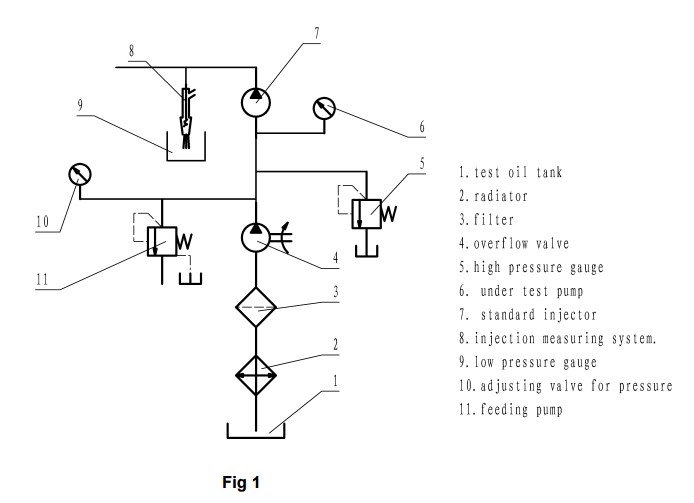
6.2.2 Working process
The working process of this system is shown as following.
6.3 Operation of the test oil system
6.3.1. Test oil
Pour 60L test oil in the tank.
The following ISO specifications test oil fluids are recommended:
- ISO 4114-1978C;
- IShell 4113;
- ICastrol 4113;
- IViscor 1487 Silkolene;
- IBrugarolas Califluid 2 (Spain);
- IAstra CP4 (Romania).
- IBosch OL 61 V1;
If the test plans require using another test fluid, these recommendations will be considered.
When additional test fluid is required, the same class of test fluid should always be used.
6.3.2. Start Pump Motor to Feed Test Oil
After the tested pump is connected to the test bench or the union of feeding oil is blocked up, start the pump motor. At the first starting time, you must pay attention to the rotation of the pump motor. The rotation must be in the same direction as indicator by the arrow on the feeding pump’s body. If not in the same , you must change the position of two phase of electrical supply on the terminal board.
6.3.3 Controlling System of Test Oil Temperature.
Switch “OIL TEMERATURE” to “ON” , the LED will light use “UP” and “DOWN” key to set the temperature.
6.3.4 Adjusting the Pressure of Test Oil
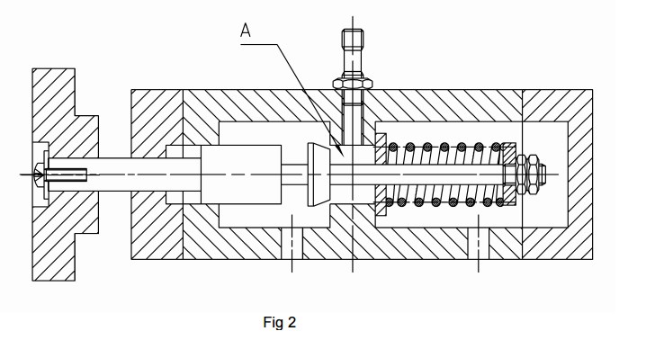
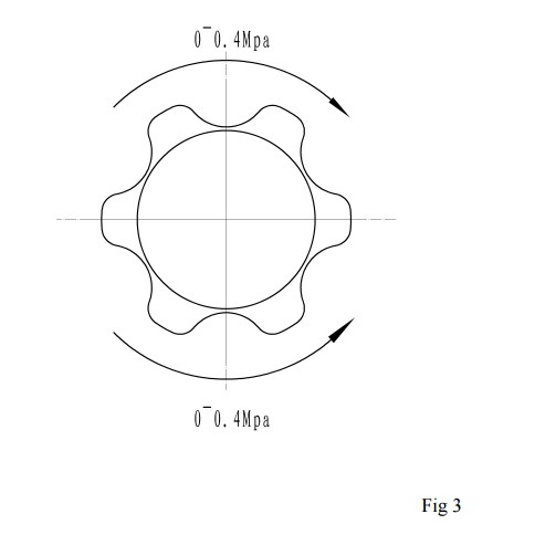
The adjusting valve could adjust not only the low pressure, but also the high pressure. The structure of this valve is shown as Fig 2. When the valve’s bar moves to the left, the adjusting spring will be compressed, so the pressure of the test oil will be raised. The pressure range is from 0 to 0.4Mpa. When the valve’s bar move to the right, the awl of the valve’s bar will gradually comes to the “A” position, the area of oil flow will be gradually reduced, so the high pressure will raised. While the area of oil flow is reduce to zero, the high pressure will be at it’s MAX. the MAX . high pressure has been adjusted to 4Mpa in the factory, so the range of high pressure is from 0 to 4Mpa.
The operation of adjusting is shown as Fig. 3
7. PNEUMATIC SYSTEM
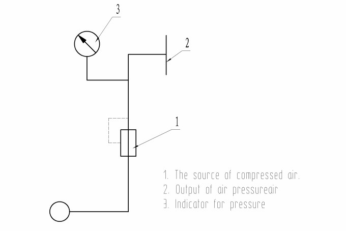
7.1 Principle Drawing
The principle drawing is shown as Fig.4
7.2 Use of Pneumatic System
Checking and Feeding of Pneumatic Boosters
Connect the booster of the pump under test to control panel’s union pipe by means of special tube.
By turning the valve of pressure air to get pressure value which the under test pump needed. Than make checking.
8.DESCRIPTION OF THE CONTROLS for 12PSB SERIES
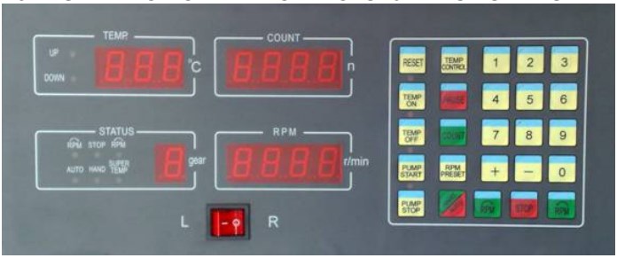
AUTO-MEASURING CONTROL PANEL
DIESEL PUMP TEST BENCH MODEL 12PSB MULTI FUNCTIONS CONTROLLER
8.1 Brief instroduction9
12PSB-III model adopts the multi function controller which is support the test bench adjusting speed through the changing frequency. This kind of controller adopts the advanced Single-chip computer control technology. It can test the oil quantity and display it, and control and display the rotational speed, count control, and temperature display, and adaptive capacity, to adapt to different test bench and different classes control. Increase the unique anti-jamming technology, work reliable and stablity, can adapt to any brand of frequency converter.
8.2 Characteristi and Technical Parameters
- Save the ten team main motor pre-set rotational speed
- Switch the rotate speed directly by the digital numbers
- Fine-turning apiece rotate speed with (+) (-) key at running
- Input apiece paramters enactment parameter with keyboard
- Over speed protect
- Oil temperatur exceed set a limit
- Auto-modify of rotate speed warp
- Power expend: ≤20W
- Control temperature range: 0-99.9 ( precision 0.5 )
- Measuring speed range: 20-4000r/min
- Rotate speed in advance setup: 30-4000r/min
- Injection oil times: 1000
8.3 DIGITAL DISPLAY OPERATING INSTRUCTIONS
8.4 Normal working
- Pushing down the counting key, the oil-injection baffle acts and the counting meter displays the count. When the count reaches the preset value, the oil-cutoff baffle is reset automatically.
- Pusing down the pause key, the oil-cutoff baffle is reset, and when push down the counting button again, the oil-cutoff baffle will recount.
- Pushing down the positive or negative rotation key, the motor will be started in the positive or negative direction. Push down the stop key the motor will stop running.
- Pushing down the manual/ automation key, the automation convert to maual, you can adjust rotation speed with potentionmeter, pushind down the manual/automation key again, renew automation and pushing (0)-(9) segment rotate speed of main motor.
Notice: The main motor is started by pushing down the left or right key in spite of manual/ automation state of the test bench.
8.5 Modity parameters ( till the motor stops running)
- Push down the temperature key the first time, which means the temperature can be modified with the indicated lamp of the upper temperature power-on. Push down the key again;the lamp of the lower temperature is on. We can use the key of “+” or “-“ to set the needed temperature. ( Note: the upper limit temperature must be larger than the lower limit temperature.) Push down the key another time to confirm the settings and exit, where the temperature meter diaplays the current oil temperature.
- Pushing down the rotation speed key, which means the rotation speed can be modififed. The left bit nixie tube in rotation speed window twinkles, and then we can use thekey of “+” or “-“ to set the needed speed. Push down the rotation speed key another time to confirm the settings and exit, where the rotation speed meter dispalys the current rotation speed of main motor.
- Push down the rotation speed key the first time, which means the oil-injection count can be modified. The left nixie tubes in the counting window twinkles, and we can use the key of “+” or “-“ to set the needed count., Push down the count key another time to confirm the settings and exit, where the count meter displays the current oil-injection count.
8.6 Fine turning the rotation speed when the motor working.
Push the key of “+’ or “-“ each time, which means the rotation speed will increase or decrease 1 turn. If it forever preserving the rotation speed value, you can push down rotation speed to confirm the settings.
8.7 Auto-set the meter
First, push the data (5) keyboard, then the test bench is started and input (1), (5). (2) keyboard, the meter id running ( the speed of main motor is about 900 rpm) the meter will begin to self-check. The meter can automate stopping in continuous 10 seconds. If so, it means the meter finished self-checking and meter can rapidly to confirm the settings speed value. Pushing down any key again, the meter can turn into work state.
8.8 Attentions
- this product belongs to the single chip micyoco (SCM). When repairing, please contact the related the techinical person. Do not open the bos, pull out the integrated circuit components and take operating every to advoid damages on the meter when it is power-on.
- Earth connection must be good when using the meter.
- If needing to rotate in the negative direction when the motor rotates in the positive direction, please push down the stop key first and then the inversion key. The inversion key does not work when in the positive direction.
8.2 CONTOLLER CONNCTION WIRES INSTRUCTIONS.
8.2.15-PIN plug
- Pin 1 : fire wire
- Pin 2 : zero wire
- Pin 3: replay normal open of inejction count
- Pin 4: replay normal close of the injection count
- Pin 5: replay common of injection count
8.2.2 7- PIN jack
- Pin 1: ground wire of rotation speed sensor
- Pin 2: signal wire of rotation speed sensor
- Pin 3: + 5V of roation speed sensor
- Pin 6: temperature sensor
- Pin 7: temperature sensor
8.2.3 7- pin plug
- Pin 1: ground wire of advanced angle sensor
- Pin 2: signal wire of advnaced angle sensor
- Pin 3: + 5V of advanced angle sensor
8.2.4 14-Pin Plug
- Pin 1 : ground wire of grequency converte
- Pin 2 : speed regulation wire of frequency converter
- Pin 3: positive and negative common of frequency converter
- Pin 4: positive wire of frequency converter
- Pin 5: negative wrie of requency converter
- Pin 6: normal open of heating relay
- Pin 7: normal open of cooling relay
- Pin 8: common of heating and cooling relay
- Pin 9: oil pump
- Pin 10 : oil pump
- Pin 11: grounding ( with the device shell ) ( must put to earth)
- Pin 12 : left key of outer potentionmeter center
- Pin 13 : right key of outer potentionmeter center
8.3 Airway System
The air way system of the test bench is shown in fig 2.
Principle of airway system of test bench
- Positive press valve
- Positive press meter
- positive press output
- air resource
- negative press valve
- negative press output
- negative press meter
9.INSTALLATION OF THE TEST BENCH
9.1. Room Preparation
The testing system of diesel injection equipments must be placed in a special prepared room, well ventilated to dissipate heat, to prevent ingestion or excessive (and prolonged) inhalation of test fluid vapors and, in the same time, to prevent the appearance of explosive atmosphere. The environmental temperature must be 5 ÷ 35 °C (41 ÷ 95 °F) and the humidity (without condensation) 30 ÷ 80 % RH.
For the best results with test bench, allow 1 meter around the testing system. The test bench should be set up on a plane, clean and solid foundation, capable of supporting the testing system weight. Special measures for anchorage are not necessary.
The energy supply must be accomplish from a 3 phase electrical power, capable to provide, without fluctuations, the following parameters:
- supply voltage: 380 V
- frequency: 50 Hz
- supply current: - 25 A
After the arrangement of the testing system on site, place the rubber dampers underside test bench bedding
Place a spirit level on the test bench and verify the horizontal level. If is necessary, insert metal pads underside rubber dampers (2, not supplied along with the system).
9.2. Connecting to 3 Phase Electrical Supply
For the electrical supply of test bench preset a 380/50Hz 3 phase line plus earthing with current carrying capacity appropriate to the motor’s electrical intake.
It is adviseable to insert a suitable maian switch at the beginning of the cable. Then, connect power 3-phase R, S, T terminals and the earthing to the special terminal. With the door open, using the necessary caution, draw the line to the test bench.
Checking the tet oil pump motor’s rotation . It should be in the same direction as indicator by the arrow on the feeding pump’s body. If not , you must cut the electrical supply, then change the position of two phase of electrical supply on the terminal board. This equipment should be installed by qualified electrical personnel only.
9.3. Filling the Test Fluid Tank
Pour 60L test oil in the tank.
The following ISO specifications test oil fluids are recommended:
- ISO 4114-1978C;
- Shell 4113;
- Castrol 4113;
- Viscor 1487 Silkolene;
- Brugarolas Califluid 2 (Spain);
- Astra CP4 (Romania).
- Bosch OL 61 V1;
If the test plans require using another test fluid, these recommendations will be considered.
When additional test fluid is required, the same class of test fluid should always be used.
9.4 Compressed Air
For operation the pneumatic system, it is necessary to feed the test bench with compressed air of 0.6Mpa, by connecting the pipe union, It is advisable to insert upstream the test bench an air filtering device as well as a compressed air driver to avoid water accumulation in the pneumatic system.
10 .PERATION THE TEST BENCH
ATTENTION:
Once the flexible coupling was removed from the main shaft, in order fix the flexible coupling again a set of special tools should be used, because the coaxality between the flexible coupling and the main shaft must be within 0.05mm.
On connecting the fuel injection pump’s coupling to the flexible coupling make sure that the faces of the two joint do not make contact in order to avoid preloading or dangerous strains on the flexible disks of the flexible coupling. Do not run the test bench if the flexible coupling is not connected to the pump.
10.1 Main Switch On
Set the main switch on, this operation should light up the following:
- The current power light
- The indicators placed on the control board.
10.2 To Feed Test Oil
Once the pump under test has been connected to the test bench,proceed as followes: Run the motor of feeding oil pump by pressing the “ON” button placed on the controller, the relevant light on the controllers will be lighted.
The direction of rotation of the motors should be as the same as the feeding pump’s. If not, the 3-phase electrical power supply must be needed to change position of any two phase on the terminal board.
Set the pressure of feeding oil at the wanted value readable on the scale pressure gauge by turning the hand wheel of adjusting valve of feeding oil.
Clockwise for low pressure, 0~4Mpa.
Counterclockwise for high pressure, 0~4mpa.
By pressing the “OFF” button it will stop feeding oil, also stop the feeding pumps motor running.
10.3 Selecting the Direction of Main Motor Rotations.
By operation the selecting switch on the controller, the direction of main motor rotation can be determined.
L: left
R: right
10.4 Start and Stop the Main Motor.
By pressing the “ON” button for motor, the main motor will be in the running position. If pressing the “OFF” button the motor will be in the stopping position.
10.5. Adjusting the Speed of Main Motor
The speed of main motor can be adjusted in two different ways, i.e.:
Gradual adjusting of the speed by operation the potentiometer placed on the controller.
Ten-steps speed preset unit, by selecting suitable button (from 1 to10).
10.6 Ten-steps Speed Preset Uint
To preset the step speed:
Make the main motor is in the running position by the “ON” button for main motor.press down of one button, the relevant LED light will be lighted up. By turning the relevant potentiometer to get the fist step speed you want.
The following steps speed are done as above.
To use the steps speed:
To use the steps speed:
During the test and the main motor in running position, it will be possible to directly reach any step speed you want by pressing the relevant button (from 1 to 10)
10.7 Controlling the and Setting the Temperature of Test Oil
Turn the oil temperature switch to on, and use the upper and down arrow key to set oil temperature.
Press the upper arrow once the LED will twinkle, than use the up and down arrow key to set high lever temperature. After set the high temperature wait the LED resume display the actual temperature. Than press down arrow key the LED will twinkle. Than use up and down key to set low lever temperature. Be sure the high lever is higher than low lever.
This model test bench are design for seldom use , It only has function with heat, it hasn’t13 cooling function. It means if the oil temperature is low than the preset the resistor of heating will work. When the oil temperature is high than you want you should stop work to wait the temperature down
10.8 Counting of Stroke
By operation the hand wheel, prearrange the 45ml or 150ml graduated cylinder, depending on whether you want to check min or max capacity.
Press up and arrow key of count meter to set times of counter. You can operation it in left or right by press the left and right button.
Run the pump under tested at a low number of rotation to fill the system and than pass to teting speed.
Wait at least 3 minutes before proceeding to send the test oil to the graduated cylinder.
When changing testing conditions too, it is necessary to wait a few dozens of seconds before reading out.
Make sure the stroke number is set at the value you want. Press the “ON” button placed on the controls board, the delivery of the under tested pump will be begun counting and it will automatically stopped at the end of the value you want. If you press the “OFF” button at any time, the count will be stopped at once.
Before measuring the delivery values, it is advisable to wait for some times, always the same (20~30sec) in order to allow the stabilization of the test oils lever’s in the test tubes. After having measured each line’s delivery values, overturn the chassis in order to discharge the graduated cylinders and let them drain for about 30sec. If there are repetitive test to be carried out, it is necessary to maintain a steady draining time.
10.9 Device For Checking and Feeding Pneumatic Boosters
Connect the booster of the pump under test to the controls panel’s union pipe by means of special tube.
By turning the value of pressure air to get the pressure value which the under tested pump needed. Then make checking.
10.10. Electro-magnetic Control’s Feeding Device
It is to feed electro-magnetic controls mounted on the fuel injection pump (solenoid values and motor’s starting/stop).
By operation the selector of DC12V/24V supply preset the testing tension at 12V or 24V according to the operation to the operation device.
Connect the electric sockets placed on the control panel to pump’s solenoid by mean’s of little cable supplied with the test bench.
A fuse protects the system in case of short circuit.
10.11 High Pressure Static Timing Device
Disconnect the return tube from the pump’s body and plug the union for test oil return.
Turn on the drain cock on the injector body corresponding to the cylinder to be analyzed.
Feed test oil and operate the hand wheel of test oil pressure adjusting valve, so that the pump’s delivery value opens and the test oil is discharged from the injector.
Set the nonmember 1 cylinder in delivery starting position by means of the special support.
Remount the delivery value as well as the delivery coupling and connect, then the high pressure pipe.
Rotate the driving coupling, by using the lever, according to the pump’s direction of rotation to find the point where the oil stops flowing from the injector.
Mark it on the casing’s graduation using the moving fiducially mark. Since this the number 1 cylinder’s delivery starting point. It also the beginning for timing the following lines which, according to the injection order, must move from this value exactly because of the angle obtain from the position of the cylinders.
10.12 Operation the Emergency button
Once you press down the emergency button, the main motor, the feeding oil motor and the controlling system of test oil temperature will stop working at once. If you want to operation the test bench again, you must reset the emergency button according to the direction marked on it.
11. MAINTENANCE
The recommended periods to accomplish the routine maintenance for the testing system, to be operated in optimal conditions, are presented in the following.
11.1. Routine maintenance
Before starting-up the system, ensure solving any occurred problems and control whether14 or not the following requirements are accomplished:
- The power cable has undamaged isolation;
- The connection to the protective earthling system is undamaged;
- The power cords and communication cables are correctly connected to the testing system and are secured against accidental disconnection;
- The test fluid level in the tank is optimal (2, figure 3.5). When additional test fluid is required, the same class of test fluid should always be used;
- There are no test fluid leakages;
- All access panels and doors are fitted and locked.
11.2. 20 Hours Drive Running Maintenance
Accomplish the operations presented in chapter 12.1 and the calibration of the RC-ST4x testing system as shown in chapter 6.1.1.
11.3. 100 Hours Drive Running Maintenance
Accomplish the operations presented in chapter 12.2 and check the injectors for the fuel injection pumps testing as well as the test pressure lines.
Use an injector tester (e.g. PG -40) to test and regulate each injector. The injector must be set to an opening pressure of 175+2 bars. In the same time the quality of the spraying process is evaluated.
Finally check the test fluid deliveries scatter between injectors, which must be of maximum 0.5 mm3/stroke. Replace the inadequate injectors with others of the same type. The test pressure lines with distorted sealing cones or holes must be replaced with similar ones.
11.4. 200 Hours Drive Running Maintenance
Accomplish the operations presented in chapter 12.3, and then change the test fluid and the filters.
To accomplish these operations, open the bolts (1, figure 3.4) mounted on the big access doors.
Remove the filters, clean the sealing surfaces and fit new filters of the same type (or technically equivalent).
After replacing the test fluid and the filters, clean up immediately all spillages of test fluid in the test area.
At this moment, check and regulate the manometers mounted on the test bench, if needed. When manometers’ indications are not in accordance with the accuracy class, the manometers will be replaced with new ones of the same class.
Perform a detailed checking of the power supply.
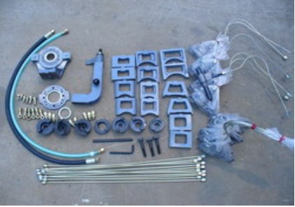
| Номер/NO. | Название/Name | Спецификация или символ/Specification or Symbol | Количество/Quantity | Единица/Unit | Поправка/Remark |
| 1 | Топливный насос высокого давления Испытательный стенд /Fuel Injection Pump Test Bench |
12PSB | 1 | Set | |
| 2 | Стандартный Инжектор /Standard Injector | PB55ST42 | 12 | PC | |
| 3 | Масло высокого давления/High Pressure Oil Pipe | M14×1.5/M14×1.5×600 | 12 | PCs | With it injector itself |
| 4 | Масло высокого давления/High Pressure Oil Pipe | M14×1.5/M12×1.5×800 | 12 | PCs | |
| 5 | Маленький выпуск (мл) /Small Graduate (ml) | 45 | 12each | PC | |
| 6 | Большой выпуск (мл) /Big Graduate (ml) | 150 | 12each | PC | |
| 7 | Подача (возврат) масла /Feed(Return)Oil Pipe | M20×1.5×1000 | 2 | PC | |
| 8 | Разъем масляного насоса /Oil pump connector | M14×1.5 M12×1.5 M16×1.5 | 2each | PCs | |
| 9 | Шкала рычага /Scale Lever | 1 | PCs | ||
| 10 | Вращательный шарнир /Rotational Join | φ12.5 φ14.5 φ16.5 | 2each | PCs | |
| 11 | Универсальный угол железа /Versatile angle iron | 1 | Set | ||
| 12 | Сцепка /Coupler | IV | 1each | PCs | |
| 13 | Зажимной кронштейн /Clamping Bracket | 1 | Set | ||
| 14 | Т-образный винт /T-type screw nail | 3each | PC | One of them longer | |
| 15 | Шестигранный ключ /Hexagon Wrench | S=10 | 1 | PCs | |
| 16 | Размещение Блока /Locating Block | P7 P7100 | 2each | PCs | |
| 17 | Провод электропитания постоянного тока /DC power supply wire | 12/24V | 1 | PCs | |
| 18 | Узел пневматической трубы / Air Pipe assemble |
Technic document
| No | Name | Quantity | Unit |
| 1 | Introduction Manual | 1 | PC |
| 2 | Packing List | 1 | PC |
| 3 | Product certificate | 1 | PC |
